Here’s a simple set of useful tips that should give you all details relating to processes and normal quotations asked by manufacturers. If there is any other information you require please contact us.
General Information
Charts, conversions and other tips
| UK | Circumference (mm) | USA | Diameter (mm) |
|---|---|---|---|
| A | 37.7 | – | 12 |
| B | 38.96 | – | 12.4 |
| C | 40.53 | 1.25 | 12.9 |
| D | 41.78 | 1.75 | 13.3 |
| E | 43.04 | 2.25 | 13.7 |
| F | 44.3 | 2.75 | 14.1 |
| G | 45.55 | 3.25 | 14.5 |
| H | 46.81 | 3.75 | 14.9 |
| I | 48.07 | 4.25 | 15.3 |
| J | 49.32 | 4.75 | 15.7 |
| K | 50.58 | 5.25 | 16.1 |
| L | 51.84 | 5.75 | 16.5 |
| M | 53.09 | 6.25 | 16.9 |
| N | 54.35 | 6.75 | 17.3 |
| O | 55.61 | 7.25 | 17.7 |
| P | 56.86 | 7.75 | 18.1 |
| Q | 58.12 | 8.25 | 18.5 |
| R | 59.38 | 8.75 | 18.9 |
| S | 60.63 | 9.25 | 19.3 |
| T | 61.89 | 9.75 | 19.7 |
| U | 63.15 | 10.5 | 20.1 |
| V | 64.4 | 10.75 | 20.5 |
| W | 65.66 | 11.25 | 20.9 |
| X | 66.92 | 11.75 | 21.3 |
| Y | 68.17 | 12.25 | 21.7 |
| Z | 69.43 | 12.75 | 22.1 |
| Palladium (950) | Platinum (950) | 22ct Yellow | 18ct White (High P. 13.5%) | 18ct Red (5N) | 18ct Yellow (2N) | 14ct White | 14ct Yellow | 9ct White | 9ct Red | 9ct Yellow | Sterling Silver | Wax | |
|---|---|---|---|---|---|---|---|---|---|---|---|---|---|
| Wax Resin | 12.000 | 21.211 | 18.737 | 16.632 | 15.948 | 16.422 | 14.948 | 14.369 | 13.264 | 11.895 | 11.685 | 10.895 | 1.000 |
| Sterling Silver | 1.101 | 1.980 | 1.745 | 1.545 | 1.480 | 1.525 | 1.385 | 1.330 | 1.225 | 1.095 | 1.075 | 1.000 | 0.092 |
| 9ct Yellow | 1.027 | 1.905 | 1.670 | 1.470 | 1.405 | 1.450 | 1.310 | 1.255 | 1.150 | 1.075 | 1.000 | 0.933 | 0.086 |
| 9ct Red | 1.009 | 1.885 | 1.650 | 1.450 | 1.385 | 1.430 | 1.290 | 1.235 | 1.130 | 1.000 | 0.983 | 0.916 | 0.085 |
| 9ct White | 0.905 | 1.755 | 1.520 | 1.320 | 1.255 | 1.300 | 1.160 | 1.105 | 1.000 | 0.897 | 0.881 | 0.822 | 0.076 |
| 14ct Yellow | 0.835 | 1.650 | 1.415 | 1.215 | 1.150 | 1.195 | 1.055 | 1.000 | 0.924 | 0.828 | 0.814 | 0.759 | 0.070 |
| 14ct White | 0.80s | 1.595 | 1.360 | 1.160 | 1.095 | 1.140 | 1.000 | 0.962 | 0.888 | 0.796 | 0.814 | 0.759 | 0.067 |
| 18ct Yellow (2N) | 0.731 | 1.455 | 1.220 | 1.020 | 0.972 | 1.000 | 0.911 | 0.875 | 0.808 | 0.725 | 0.712 | 0.664 | 0.061 |
| 18ct Red (5N) | 0.752 | 1.500 | 1.265 | 1.065 | 1.000 | 1.030 | 0.938 | 0.901 | 0.832 | 0.746 | 0.733 | 0.684 | 0.063 |
| 18ct White (High P. 13.5%) | 0.722 | 1.435 | 1.200 | 1.000 | 0.959 | 0.988 | 0.899 | 0.864 | 0.798 | 0.716 | 0.703 | 0.656 | 0.061 |
| 22ct Yellow | 0.640 | 1.235 | 1.000 | 0.888 | 0.852 | 0.877 | 0.798 | 0.767 | 0.708 | 0.635 | 0.624 | 0.852 | 0.054 |
| Platinum (950) | 0.566 | 1.000 | 0.884 | 0.785 | 0.752 | 0.775 | 0.705 | 0.678 | 0.626 | 0.561 | 0.551 | 0.514 | 0.048 |
| Palladium (950) | 1.000 | 1.768 | 1.561 | 1.386 | 1.329 | 1.369 | 1.246 | 1.197 | 1.105 | 0.991 | 0.974 | 0.908 | 0.083 |
Vulcanised Moulds
This form of mould making is the most common for jewellery applications as the rubber can withstand years of injecting without distortion. Vulcanised moulds are produced using natural rubber where heat and pressure is applied. Once the rubber has cooled the moulds are cut into 2 halfs. Some complicated moulds may have to be cut into more pieces to allow the object to release more easily.
Vulcanised moulds have a shrinkage of around 2-4% depending on the size of the piece. Please contact us for more details and recommendations.
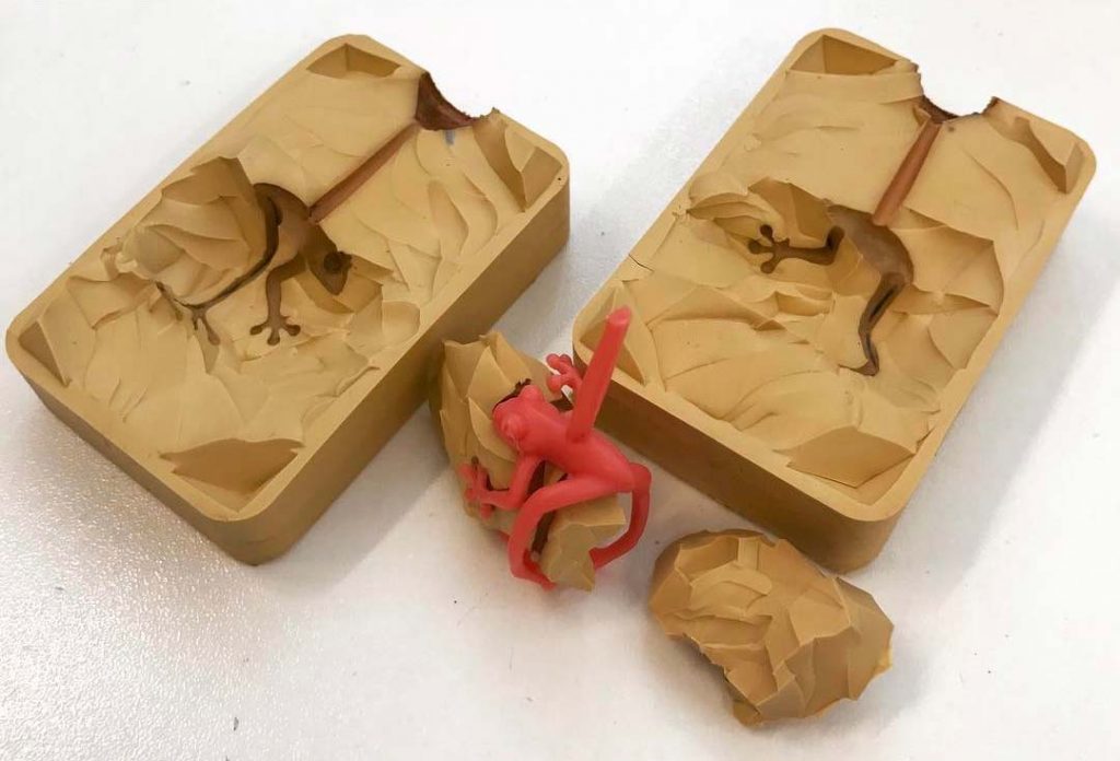
Cold Moulds
Cold moulds are used normally on organic objects that cannot withstand heat and pressure. Made from a 2 part silicon rubber that is poured into a mould that your piece is within. The cutting of the mould is the same as the vulcanised process.
There is very minimal shrinkage with could moulds, around 0.5-1%. Please contact us for more details and recommendations.
Hallmarking Weights
Items below the following weights are exempt from Hallmarking:
- Silver 7.78 grams
- Palladium 1.0 gram
- Gold 1.0 gram
- Platinum 0.5 grams
3D / CAD Design Rules
Simple design tips to help you get started
Here, we have compiled a few of the most common CAD challenges and a few pointers to help you on your way to realising your concept/design.
Making sure your file is printable
Your 3d model has to to be watertight and have no exposed (naked edges). Naked edges cause computational errors when the file is to be printed. Below are a few basic examples and guidelines to ensure your file is printable right off the bat.
All parts must be booleaned (unified) together as a single part to be printed – (more parts may be required depending on the complexity of the design and manufacturing strategies in place).
Figure 2. has all of the parts as separate – there is a possibility when printing that they will fall apart in their component parts.
Figure 3. shows the same ring as a single part and is watertight with no manifold edges (shared edges and corners – we’ll explain this a little later on). This is a watertight, solid model that can be exported as an .STL format file ready for 3d printing.
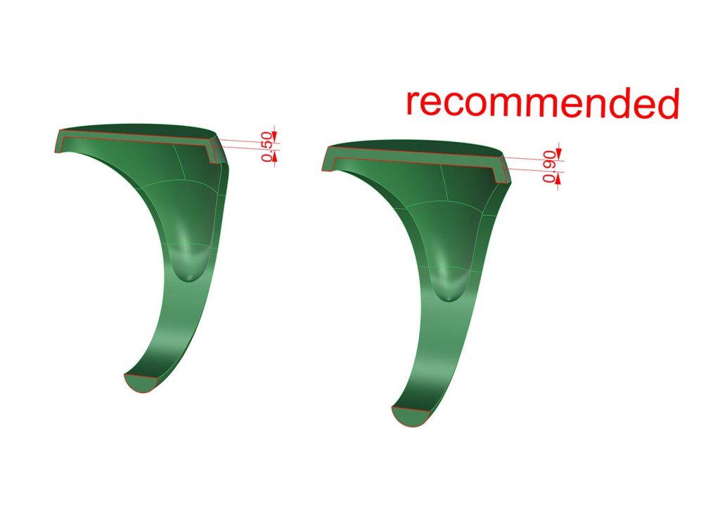
Thicknesses are important
General thicknesses in CAD must be thicker than if you were to make it by hand. We have to consider the processes involved in the production of the piece and effectively work backward to decide relevant thicknesses of parts or an entire piece.
Let’s take this cross section of this hollow signet ring in figure 1. as a working example.
If we know that this needs to survive 3d printing – casting – cleanup and polishing. The 0.50mm could possibly survive all of the processes but chances are when complete it will be wafer thin and extremely flimsy (nobody wants to give anyone – even your mother – a flimsy piece of jewellery).
We wish we could tell you a perfect thickness that will answer all of your questions (fact of the matter is; there isn’t one) – what we can tell you is thicker is better as you can always file metal away after casting. And in this case 0.90mm will be a much better choice than 0.50mm.
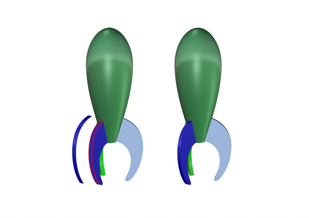
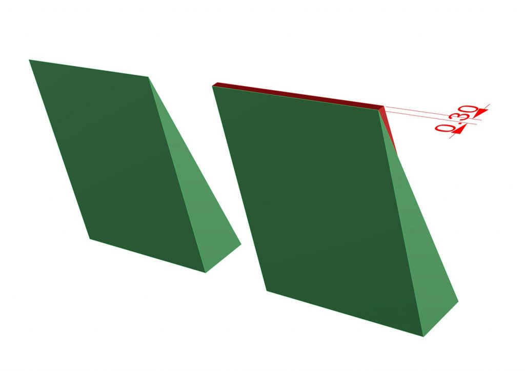
Things coming to points
We’ve all fancied having a little part of a piece of jewellery where we want a lovely sharp edge – almost a knife edge…
General rule in CAD is NO!!! Things coming to points are never a good idea. As we touched on briefly earlier about thicknesses and there being no general rule for thicknesses – in this case there is – see the images.
There are a few issues that arise when we create items that come to points:
Firstly, when the part goes to being cast the metal has to work very hard filling that edge (often the surface tension of the liquid metal will inherently restrict it reaching the very fine point leaving you with what seems like a not quite filled casting (not good for anyone).
The recommendation is that we add enough material to allow it to fill and then in the manufacturing process file it back to that point that was once desired.
In Figure 2. you can see we’ve added the blue portion, a small addition to the already existing example. This allows us, like before, to file back if necessary also if this technique was applied to a motif style of detailing the point will look like it’s coming to a point from the front and will have sufficient material to last the test of time.

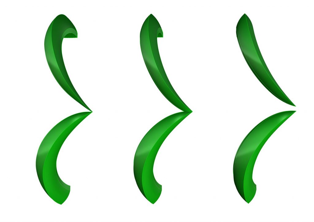
Edges and corners that touch
A good rule of thumb when modeling is to have edges are are independent (ie. not touching and/or edge being shared between two objects).
In figure 1. the three images illustrate the options of solving the issue of having a ‘non-manifold’ edge (shared, touching or overlapping edges). The first image shows points touching which will cause issues as the recorded thickness at that point in 0.00mm.
Options to resolve this is to thicken them up and overlap each other to creating a point with thickness that will be robust enough to survive the processes involved (3d printing, casting, clean up etc…) Also, you can bring them apart so that the pieces are not touching. Thusly resolving the non manifold issue but now opening another challenge which we’ll explain next.
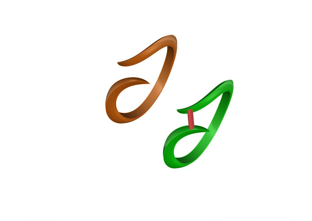
Supporting your model
If your model is an open ring, for example a tension set or a one size fits all ring, it’s very important that the model is supported adequately so that it doesn’t break and/or bend at any point. Making fitting parts together very difficult and creating a lot more work in the finishing process than is necessary. All of this can be minimised/avoided with a very quick fix in the CAD.
A very simple bar to bridge the gap between the two open sides has just massively increased the chances of your cast model being faithful to your CAD drawing. This can be kept in until you decide the time to remove it. Be sure to make it thick enough to cast and function as a support bar (the thicker the better, 1.00mm is a good figure to start with).
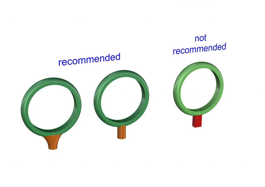
Spruing strategies
Spruing ‘correctly’ is one of the most important parts of the casting process. It is the gateway that allows molten metal to flow into your piece.
The advantage of adding your sprue in CAD is that the connections are crisp and extremely defined. Have a look at the images for a quick guide to spruing in CAD.
In the third ring the sprue here is square – as a rule round is much preferred to square. It allows the metal to flow much more freely into the piece and pulling in less air on its way and reducing the amount of porosity.
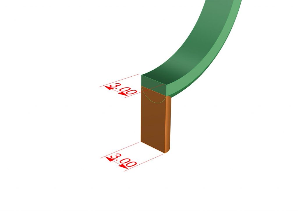
Another general rule in your CAD spruing is to keep the sprue as wide as possible. Note that the sprue cross section is the same as that of the ring shank.
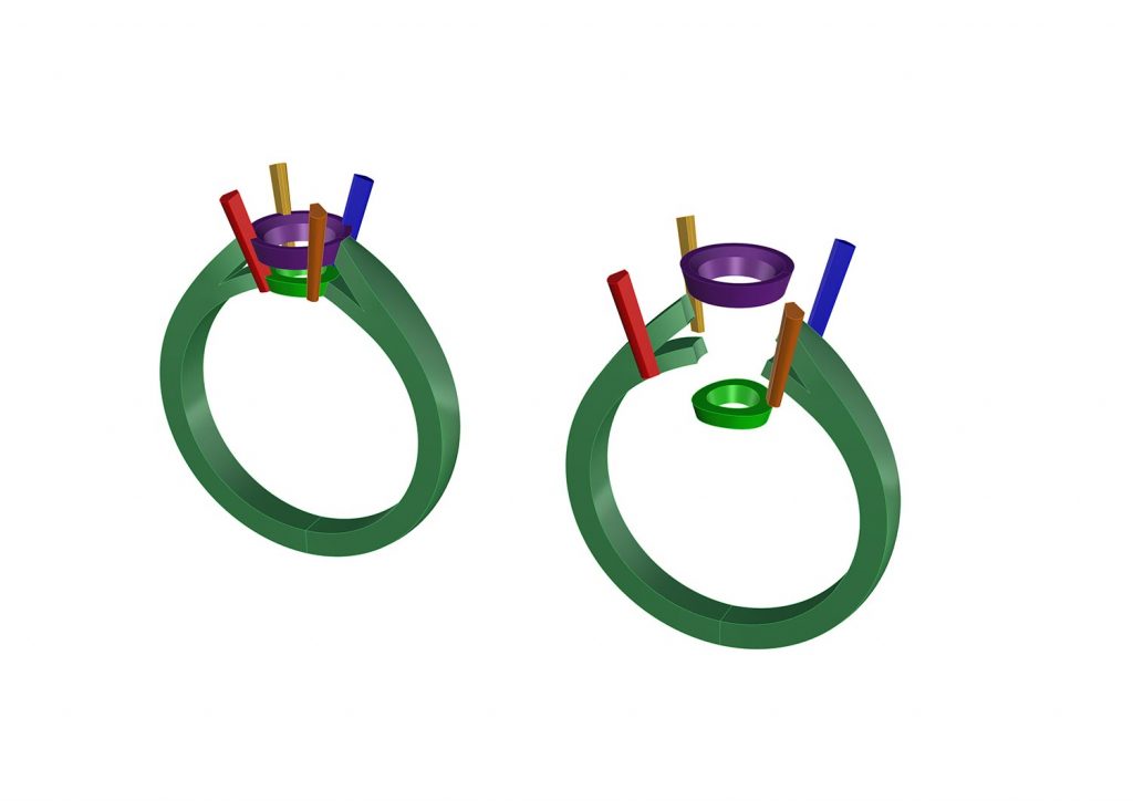
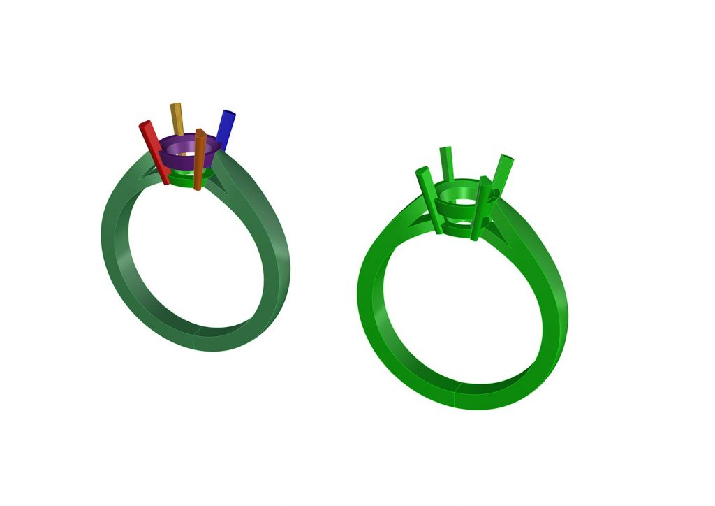
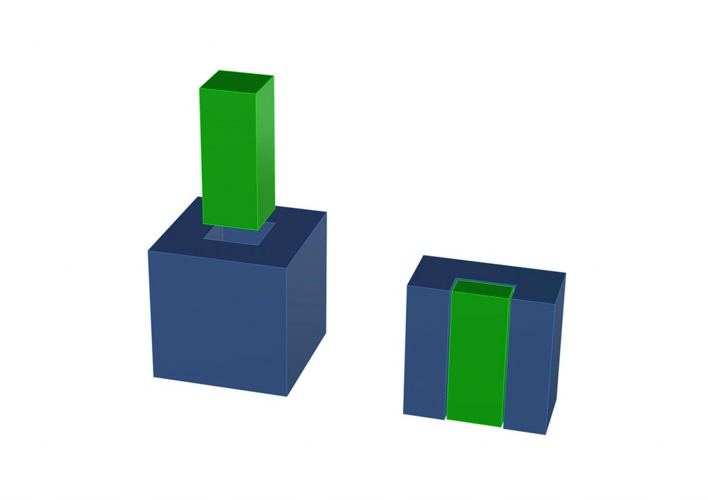
Designing parts with manufacturing in mind
This part can be a little daunting for people not used to the production process. Follow a few simple rules and your piece will come together like a dream. We had mentioned before it’s always better to have more than less so that we can file and fit things into place.
We’ve illustrated below what we mean in the first image.
In this image we can see the desired parts on the left and on the right they are shown after the have been filed and buffed. Note that because the pieces in the first image show them exactly fitting, the cleanup process has taken metal off both objects and now they do not fit and rattle inside one another.
In the image below we have compensated for this cleanup process by adding a very small amount of material to both parts in this case, 0.05mm on all sides. This allows us to file both parts back to fit exactly inside one another making for a better overall final product.
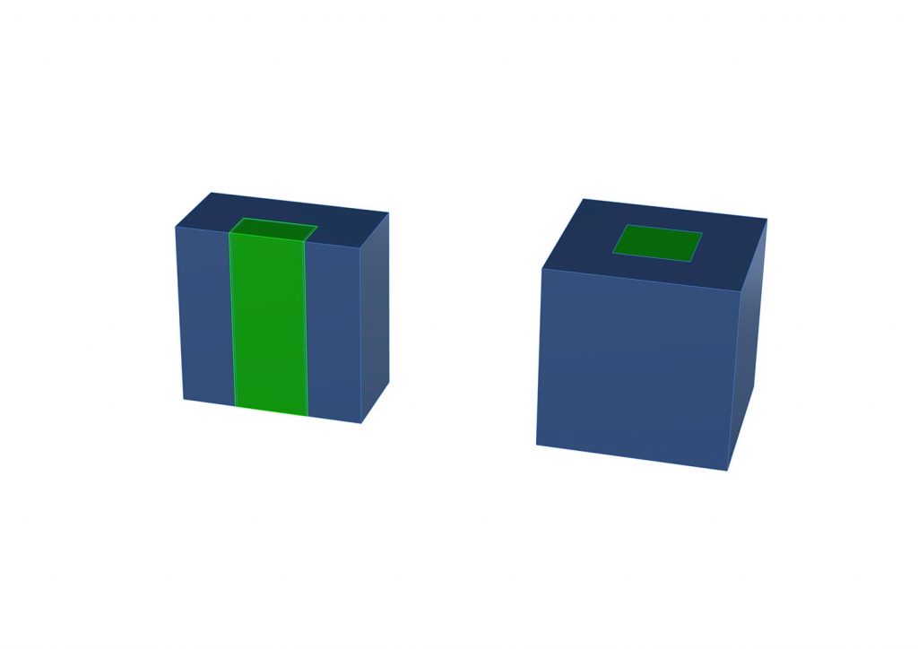
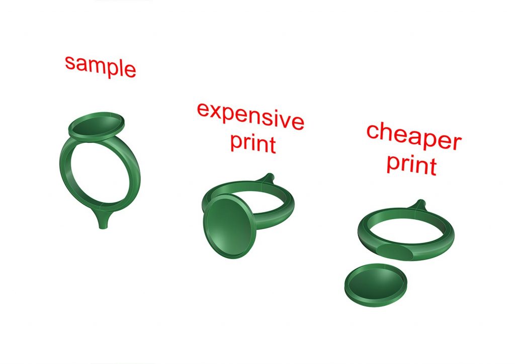
Cheaper prints
So you’ve designed your piece and now is almost the moment of truth, having it prototyped.
3d printing can be very expensive if not taken into consideration in the design process.
Pricing of 3d printing calculated by the time it takes to print the object. As it lays down layer on top of layer to eventually leave you with your product. The more layers (the taller) something has the more expensive it will be. As mentioned before it’s important to take into account the decimation process to stop your wallet from taking an unexpected hit – We’ve quickly illustrated this.
Note the height difference between the last two images. One will cost around £65 and the other around £40… every small saving helps. So try and keep them low. Not always applicable but definitely something to keep in mind.
Get a Quote
Choose 1 of the following options
